


|
INSTALLING XL CAMS
|
Quick Links:
|
Introduction
 Changing cams is part of almost every high performance project, simply because the factory cams generally start limiting you before you make it very far down the path of modifying your motor. Cylinder fill is the name of the game, and cams play a huge role in that, by both the timing of when they open and close
valves and also how much they open them. When you start leaving power on the table by virtue of your stock cams, it's time to change them. Changing cams is part of almost every high performance project, simply because the factory cams generally start limiting you before you make it very far down the path of modifying your motor. Cylinder fill is the name of the game, and cams play a huge role in that, by both the timing of when they open and close
valves and also how much they open them. When you start leaving power on the table by virtue of your stock cams, it's time to change them.
We want your project to be a success, so this article is provided to show all the ins and outs of swapping cams on an XL motor. If we missed something, or if
you have any questions, don't hesitate to contact us, we're happy to help.
|
Cam Specs and How They Affect Installation
Swapping your cams can be very simple or very complex or anywhere in between. The complexity level is directly related to the cams you're trying to install, and for that information,
you'll need the cam spec sheet.
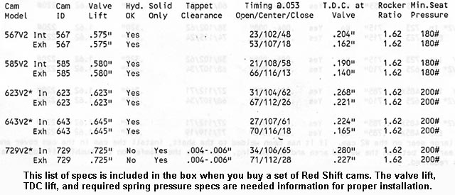
Here's what to look for on the spec sheet:
TDC Lift: Contrary to popular belief, maximum lift has no bearing on valve-to-piston clearance, because max lift occurs with the piston well down the bore. No, if you want to understand whether or
not a set of cams is going to get you in trouble on valve-to-piston clearance, TDC lift is the spec you're interested it. It's exactly as the name implies, how much the valves are open at top dead
center (TDC), in this case overlap TDC, not compression TDC (overlap TDC occurs between the exhaust and intake strokes).
Overlap can be a wonderful thing in a set of cams, as it effectively connects the exhaust system to the intake tract and gives the exhaust an opportunity to pull on the intake charge at the front of the intake
stroke, thus getting it moving before the piston even starts pulling on it. However, cams with a big overlap window (intake open point plus exhaust close point) also tend to have big TDC lift numbers, and this is what
gets you into trouble on valve-to-piston clearance. It can also get you into trouble on valve-to-valve clearance, which is a big reason that the person who prepares your heads should know what cams you're using.
Look for TDC lift specs in excess of .220" on either valve, that's about where you really start pushing things, particularly if you're using stock pistons with their smallish valve pockets.
With a quality aftermarket piston like the HAMMER PERFORMANCE Sledge Hammer pistons, you can handle quite a bit more TDC lift without getting into trouble.
Maximum Lift: OK, so max lift won't get you into trouble on valve-to-piston clearance, but that doesn't mean a big max lift number is trouble free. Lifting farther can cause a whole host of
issues, including:
- Lobe swing clearance in the cam box
- Tappet anti-rotation pin clearance
- Rocker arm to rocker box top clearance
- Valve spring retainer to guide seal clearance
- Valve spring coil bind clearance
- Rocker arm geometry issues
Each of these things can be addressed, of course, and they're described in more detail below, but when selecting cams, keep in mind that the higher the max lift spec, the more likely you are to get into
trouble on these things. In general, for a 1986 to 2003 Sportster, or for a 1984 to 2004 Big Twin or Twin Cam, up to .500" of valve lift is considered safe on the stock hardware. For 2004-up Sportsters, or 2005-up
Twin Cams, .550" of lift is considered the safe limit, although smaller base circle cams may be needed.
Base Circle: This is a spec that's almost never published, yet it has a very real effect on clearance issues. In a nutshell, when a cam is not pushing up on a lifter, it has a base radius that
defines how much the lifter is being held up. Cams with a smaller base circle have a smaller radius in the valve closed position.
So what does that do for you? Well, lift is the difference between the cam's radius on the base circle and the cam's radius on the nose of the lobe. That means you can achieve more lift in two
different ways: you can either make the lobe taller (the most common way), or alternatively, you can make the base circle radius smaller. The latter may require longer pushrods to match, but often the top
end of a Harley motor ends up getting lowered anyway, via head milling and/or thin gaskets to improve squish clearance. Pushrod length is a whole subject in and of itself and is discussed in a separate article.
The advantage to a smaller base circle is that it achieves higher lift without causing issues with lobe swing or tappet pin clearance. The disadvantage is that is gives the cam lobe a less desirable angle
of attack on the lifter roller, which can limit the cam designer in terms of valve opening rates. This is why you rarely see small base circles on very high performance cams. It can also, on occasion, cause an
issue in the cam box where the lifter gets hung up on the cam bushing and doesn't come down far enough to rest on the cam. This is fairly simple to detect and correct, but still, it's something you need to
watch for when using small base circle cams.
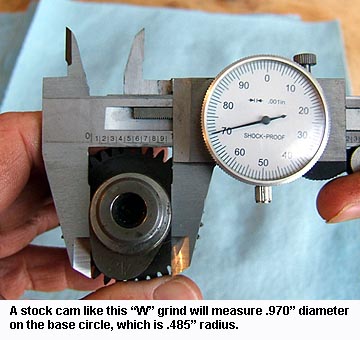
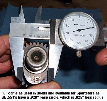
In the world of XL cams, the grinds you'll find with smaller than stock base circles are mainly the Screamin Eagle .551 and .575 lift grinds, and the Andrews N9. If you're not sure, try to measure the diameter
of the cam (on broad cams it's difficult to measure the diameter because the lobe goes more than halfway around). Stock diameter is .970", which is a radius of .485".
Valve Spring Pressure: Sometimes a cam maker will specify a minimum valve spring pressure, and when they do, it's almost always seat pressure as opposed to open pressure. Required spring pressure is a
function of ramp rates and intended rpm, and if the springs can't keep up, seat bounce or valve to piston contact can result, so this is a critical number. But it's also just a guideline, as there are multiple
things that can affect the seat pressure needed to keep the valvetrain under control, most notably the weight of the various pieces of the valvetrain. Still, it's a good baseline number to consider. Unfortunately,
not nearly enough cam makers bother to publish it.
Bolt-In: The term "bolt-in" is used very commonly by the cam companies to tell you they believe the cams will go right into an otherwise stock motor, just like the stock cams, without concern for the
clearance issues described here, and will also work fine with the stock valve spring pressure. Bolt-in cams are generally what you want if your heads are still stock or Impact level prepared. But if you've had your heads prepared
to the Smash, Crush, or Sledge level, you'll leave power on the table when using bolt-in cams.
|
Basic Cam Installation
In this section, we'll walk through the mechanics of a basic cam installation. The information here applies to all cam installs, mild to wild, and in the case of bolt-in cams, this will cover it.
If your cams aren't bolt-in, however, read the "Advanced Cam Installation" section below for additional things you may need to do. Also note that this information is not intended as a replacement for the
factory service manual, but rather as a supplement to it. A factory service manual is an essential tool and you should not tackle this job or any other engine work without one handy.
Disassembly: Okay, so from the outside, it looks simple enough. There's a cover over the cam box, and after removing the foot peg and possibly the exhaust, all the screws are accessible.
 You might be tempted to start removing screws and pull the cover off. Well, STOP right there.
That cover is much more than just a cover; it actually supports the outboard end of the cams. There's valve spring pressure being transmitted onto at least some of those cams at all times, no
matter what position the engine is in. So if you pull the cover without first removing that valve spring pressure, you've created a situation where the cams lose their outboard support and get torqued downward,
putting the inboard bushings at great risk. Even if you manage to avoid damaging the inboard bushings, you're still not going to get the old cams out and the new cams in with all that spring pressure
pushing down on the lifters. So don't even think about pulling that cover yet!
To get the valve spring pressure off the cams, you need to remove the rocker boxes that sit on top of the cylinder heads. It's very straightforward to remove them, as there's 4 cover screws and then another
 9 bolts holding each box down, but you do need to position the motor properly before removing each. The correct position is compression TDC (or thereabouts). If you don't know how to tell compression
TDC from overlap TDC, read this. Position the cylinder at compression TDC, remove the rocker box, then position the other cylinder at it's compression TDC
and remove it's rocker box.
9 bolts holding each box down, but you do need to position the motor properly before removing each. The correct position is compression TDC (or thereabouts). If you don't know how to tell compression
TDC from overlap TDC, read this. Position the cylinder at compression TDC, remove the rocker box, then position the other cylinder at it's compression TDC
and remove it's rocker box.
So now that we've taken the valve spring pressure off, we're ready to go downstairs and get the cover off. It's a good idea to put an oil drain pan under the cover area, because when you pull the cover, some
oil will invariably drain out of the cam box. If your bike is an '03 or older, start by removing the timing cover (drill rivet heads off with a 1/4" drill bit).
Under the cover you'll find another plate that comes off with two phillips head screws, and under that is your timing plate. Take a sharp knife and mark the cover and the plate such that you know exactly where it was,
rotationally speaking. Remove the timing plate and the rotor cup that sits under it. Note that the rubber mount bikes did away with the timing plate, so no need to look under the timing cover, there's nothing in there.
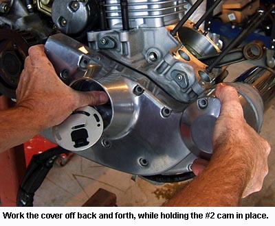
Now remove the cover screws. There are 11 of them. It may take some gentle persuasion with a rubber mallet to get the cover to come loose, just be careful, don't pry or anything like that as you risk tearing something
up. On the '03 and older bikes, when the cover starts to move away from the crankcase, you can put a thumb over the end of the #2 cam (the one the rotor cup was bolted to) to hold it in place in the engine as you
work the cover off. This isn't strictly necessary, but it does help keep the cams from falling onto the floor or into your oil drain pan. You can often just leave the cover attached by it's vent hose and swing it out of the way.
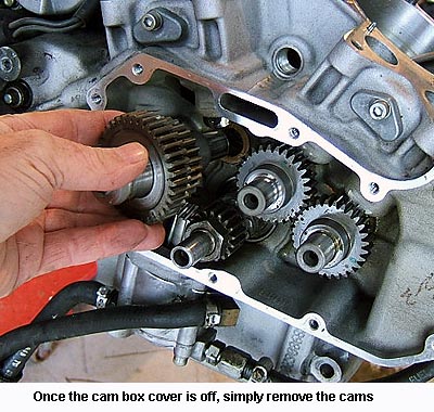
Now you're looking at your cam box, presumably with all four cams still in place. Remove them one by one, noting that the #2 cam (the cams count from back to front in an XL, front to back in an XB) must come out first before
the #1 and #3 cam can be removed. Set them on a clean rag.
The final disassembly step is to remove the pinion gear and oil pump drive gear, neither of which is strictly necessary when swapping cams, but there's a method to my madness, read on. Caution: Do not
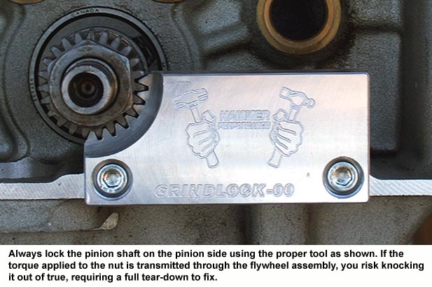
loosen the pinion nut by holding the flywheel assembly on the opposite side by any method! This includes putting the bike in gear and holding the brake. Doing so transmits the torque applied through the flywheel assembly
in a way that it was never designed to handle, and it can easily throw the flywheels out of true, necessitating a full tear-down to fix it. Instead, lock the flywheel assembly on the cam box side using
the correct pinion locking tool. This is critical!
Cam Gear Tooth Pitch: Something to be very aware of when swapping XL cams is that
Evolution XL's have come with 3 different arrangements for tooth pitch on the cams:
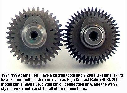
- 1986-1999 models came with a coarse tooth pitch: 18T/36T pinion connection and 28T/28T between the cam gears.
- 2000 models came with a mix of coarse and fine tooth pitch: 23T/46T pinion connection and 28T/28T between the cam gears.
- 2001-up models came with a fine tooth pitch: 23T/46T pinion connection and 35T/35T between the cam gears.
Since cams are typically installed in full sets, it's the tooth pitch on the pinion connection that you need to make sure matches. An aftermarket cam set designated as fitting a 2000-up motor will have a fine tooth
pitch, commonly referred to as a High Contact Ratio (HCR) gear cut, on the drive gear that meshes with the pinion gear. The interconnecting gears may be coarse or fine. Likewise, a cam set designated as fitting a
1986-1990 (4-speed) or 1991-1999 model will have a coarse tooth pitch on the drive gear that meshes with the pinion gear, and probably all the others as well.
Note that 1986-1990 cams (4-speeds) are not interchangeable with 1991+ cams (5-speeds). Despite a similar tooth pitch, 4-speeds use offset tappets, where 5-speeds use on-center tappets, so it's a whole different animal.
Don't go there.
However, among 5-speeds, interchangeability is possible across all year ranges.
If you have a cam set that's made for an 00-up model and you want to put it into a 91-99 motor, all that's really necessary is to update the pinion gear.
The opposite is also true, to fit 91-99 cams into an 00-up motor, you can simply backdate the pinion gear.
HAMMER PERFORMANCE offers pinion gears of both gear pitches to facilitate this sort of swap.
There's another method for dealing with the gear tooth pitch issue as well. The large drive gear on the #2 cam that meshes with the pinion gear can be pressed off of your old #2 cam and pressed on to your new
#2 cam. For instructions on how to do this, read this article.
Cam Gear Fit: As described above, 1986-1999 cam gears use a coarser gear pitch on the cams. Likewise, many aftermarket cam sets, even those made for 2000-up motors, use this coarser tooth pitch at least
on the connections between the cams.
 Well, this gear tooth pitch required very precise fitting at the factory to minimize cam gear noise. The number 1, 3, and 4 cams for 1986-2000 models were available in literally 7 different sizes each. The number
2 cam, with it's 2 gears, was available in a whopping 49 different sizes, 7 for the main drive gear times another 7 for the gear that drives the other cams (note that 2000 models only needed 7 different #2 cams since
the main drive gear went to the HCR style tooth cut). Harley would precisely measure every engine crankcase and cam cover
combination and choose cams that were a perfect fit for that motor, all in the name of noise reduction. The HCR
style tooth cut, introduced at the pinion connection in 2000 and on the rest of the connections from 2001 and on, does not require this precise fitting.
Well, this gear tooth pitch required very precise fitting at the factory to minimize cam gear noise. The number 1, 3, and 4 cams for 1986-2000 models were available in literally 7 different sizes each. The number
2 cam, with it's 2 gears, was available in a whopping 49 different sizes, 7 for the main drive gear times another 7 for the gear that drives the other cams (note that 2000 models only needed 7 different #2 cams since
the main drive gear went to the HCR style tooth cut). Harley would precisely measure every engine crankcase and cam cover
combination and choose cams that were a perfect fit for that motor, all in the name of noise reduction. The HCR
style tooth cut, introduced at the pinion connection in 2000 and on the rest of the connections from 2001 and on, does not require this precise fitting.
So if you're putting coarse tooth cams into your motor, of any year, you must verify that your cams do not bind due to cam gears that fit too tightly. Fortunately, aftermarket cams are typically provided
on the small end of the cam gear size ranges, for the simple reason that although looser fitting cams will make more noise, the noise is harmless. On the other hand, cam gears that are too large and fit too tightly
create a failure risk, as localized tooth heating can occur.
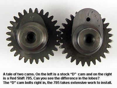
This whole cam gear fit issue is one of the reason Red Shift cams are so nice on 1986-2000 models. Red Shift takes your stock, factory fitted cams and puts new lobes on them, thus preserving the factory
gear fit. Red Shift Cams are available from HAMMER PERFORMANCE.
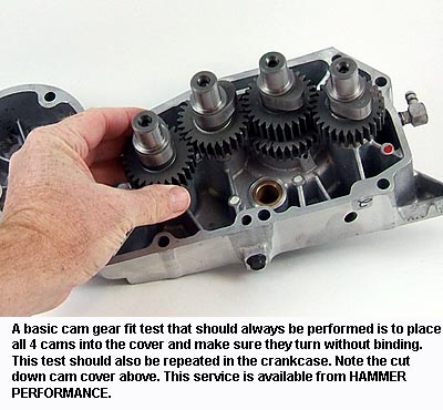
How do you go about verifying that the cams aren't too tight? There are 3 things you can do:
-
 Put all 4 cams into place in the cam cover only, with their marks aligned (a little tricky to do from that side). Make sure there's a little lube in the bushings and also on the cam gear teeth
themselves. Turn the cams by hand and make sure they turn freely, without binding.
Put all 4 cams into place in the cam cover only, with their marks aligned (a little tricky to do from that side). Make sure there's a little lube in the bushings and also on the cam gear teeth
themselves. Turn the cams by hand and make sure they turn freely, without binding.
- Put all 4 cams into place in the motor only, again with their marks aligned, and with no pinion gear installed (remember in the disassembly section how I had you remove the pinion gear?). Remove the tappets
if possible to reduce the resistance they introduce. Again, make sure you've got the bushings and teeth somewhat lubricated. Turn the cams by hand and make sure they turn freely, without binding.
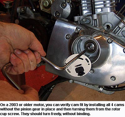
- On 2003 and older motors, you can do a third check as well. With the cams still in the motor for the second check above, put the cover into place and torque to spec, following the sequence described
in the service manual. Install the little screw into the #2 cam that holds the timing cup into place, and turn it with a socket. All 4 cams will turn, and you'll be able to feel if there's any binding.
Small Base Circles: As described earlier, cams with a small base circle let the lifter down farther.
 While this solves some problems associated with high lifts, it also introduces a couple of issues that a
cam installer needs to be aware of. I'm discussing it here in the "Basic" section because there are cams on the market, such as the SE .551 lift "E" grind cams, that are designated as "bolt-in" for certain applications,
and yet have a small base circle.
While this solves some problems associated with high lifts, it also introduces a couple of issues that a
cam installer needs to be aware of. I'm discussing it here in the "Basic" section because there are cams on the market, such as the SE .551 lift "E" grind cams, that are designated as "bolt-in" for certain applications,
and yet have a small base circle.
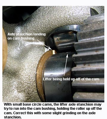
First and foremost, letting a lifter down farther can cause issues with the lifter hanging up on the inboard cam bushing (that's pressed into the case), rather than resting on the base circle of the cam. I've
seen this happen many times, you absolutely need to check for this if you're using small base circle cams. Simply turn the cam such that the lifter is let all the way down, and carefully inspect where the lifter
roller meets the cam to make sure there's no gap between the two of them. Correcting this is fairly simple. Remove the lifter and grind a small amount of material from the end of the inboard axle stanchion.
The other issue with a smaller base circle cam is that it can create a need for longer pushrods. A base circle diameter that's .050" smaller than stock (like the "E" cams) will let the lifter down an additional
.025". That's not normally enough to get you into trouble, but it could be. Read this for a more thorough discussion of the subject of pushrod length to decide if this is a concern for you.
End Play: Another check you should always make is to verify the cam end play is within spec. For most XL motors, this means .005" to .024" on the number 1, 3, and 4 cams with a service wear limit of .025", and .006" to .024"
on the #2 cam with a service wear limit of .040".
Unfortunately, this is somewhat of a difficult measurement to make on an XL motor just due to the depth of the cams below the case deck. The measurement has to be made with the cam cover installed. Insert
a feeler gauge through the tappet hole, and guide it in between the cam and the bushing in the crankcase. In the rare event that the end play is too tight, it can be addressed with a slightly thicker cam cover gasket,
which Cometic offers and HAMMER PERFORMANCE carries. If the end play is too loose, however, it indicates the bushing faces are worn and need to be replaced. This is a job best left to professionals, call us if you
find yourself in this predicament.
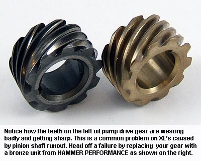 Oil Pump Drive Gear: Directly under the pinion gear you'll find the oil pump drive gear. This gear is especially prone to wear and you should remove and inspect it carefully. What you'll typically find
is wear on one side only, as pinion shaft run out causes the engagement to change with each revolution. Look for teeth that are sharpening, this is a sure sign that failure is imminent.
Oil Pump Drive Gear: Directly under the pinion gear you'll find the oil pump drive gear. This gear is especially prone to wear and you should remove and inspect it carefully. What you'll typically find
is wear on one side only, as pinion shaft run out causes the engagement to change with each revolution. Look for teeth that are sharpening, this is a sure sign that failure is imminent.
The cure for this is a bronze oil pump drive gear available from HAMMER PERFORMANCE. We highly recommend this little piece of insurance to make sure you don't have a catastrophic failure that can take out your whole motor.
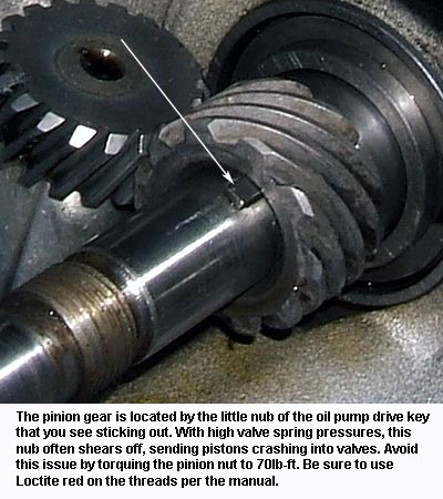 Pinion Nut: The pinion gear is located by a little nub of the key that sits under the oil pump drive gear. That little nub is not nearly strong enough by itself to keep the gear from spinning on the
pinion shaft, and instead it's the clamp load from the nut that keeps the pinion gear where we want it.
Pinion Nut: The pinion gear is located by a little nub of the key that sits under the oil pump drive gear. That little nub is not nearly strong enough by itself to keep the gear from spinning on the
pinion shaft, and instead it's the clamp load from the nut that keeps the pinion gear where we want it.
Well, the factory torque spec on the pinion nut, which is
35-45ft-lbs, has proven woefully inadequate to hold the pinion gear in place when high pressure valve springs are used. We highly recommend torquing this
nut to 70ft-lb instead. Use Loctite red on the threads per the manual, and also be sure to lock the pinion shaft on the pinion side before torquing the nut, just as you did when you removed the nut.
Again, holding the flywheel still by any method on the other side of the flywheel assembly will allow the torque applied to the nut to be transmitted through the flywheel assembly, putting it at great risk of
being knocked out of true, which requires a full tear-down to fix.
Pinion locking tools are available from HAMMER PERFORMANCE.
The pinion locking tool shown partially encircles the pinion gear for maximum strength, and therefore, it will not mesh with the pinion gear from the side of the gear. To use this tool, position the tool
over the end of the pinion gear and push it away from your body, over the end of the gear, instead of coming in from the side of the gear. This is the only way it will go on. If it's still not clear
or you're still having difficulty, click here for pictures showing how it goes on.
Final Assembly: Now that the pinion nut is Loctited and torqued back down, it's time for the final button up:
-
 Rotate the engine until the pinion gear mark (on one of the teeth) points directly to the middle of the number two cam bushing. Note that neither piston is at TDC when the engine
is positioned this way. Cam installation has nothing to do with finding TDC, as many people mistakenly assume. The correct crank position is achieved when the mark on the pinion gear is pointing
to the middle of the number two cam (cams on XL motors are numbered from back to front, on XB motors they're numbered from front to back).
Rotate the engine until the pinion gear mark (on one of the teeth) points directly to the middle of the number two cam bushing. Note that neither piston is at TDC when the engine
is positioned this way. Cam installation has nothing to do with finding TDC, as many people mistakenly assume. The correct crank position is achieved when the mark on the pinion gear is pointing
to the middle of the number two cam (cams on XL motors are numbered from back to front, on XB motors they're numbered from front to back).
- Clean the cams thoroughly. This is especially important on new cams right out of the box, as they are probably coated with cosmolene. Use a cleaning solvent, brake parts cleaner, even
gasoline will do in a pinch. Blow them off with compressed air to dry them and remove any particles.
- Apply assembly lube liberally to the cam journals, the lobes, and the gear teeth. This is important!
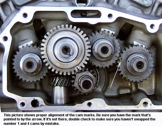
- Install the cams in their correct positions, with the marks aligned. See the picture below. Take care not to swap the #1 and #4 cams, this is an easy mistake to make. Here's a suggested sequence
of how you should go about this:
- Install the #1 cam, with it's mark pointed toward the middle of the #2 cam bushing
- Install the #3 cam, with it's upper mark (the one up by the journal) pointed toward the middle of the #2 cam bushing
- Install the #4 cam, with it's mark aligned to the mark on the #3 cam. Both of these marks should be adjacent to the gear teeth. If not, you're doing something wrong.
- Install the #2 cam. Note that it has 3 marks, one each for the #1 cam, the pinion gear, and the #3 cam. Align the pinion mark to the mark on the pinion gear and push the cam in. It will almost certainly stop
before it gets all the way in. It's stopping due to imperfect alignment between it's teeth and the teeth on the #1 and #3 cams, back behind the drive gear where you can't see it. So now, while holding light
inward pressure on the #2 cam, very slightly rotate the #1 cam as well as the #3-4 combination back and forth to allow the teeth to engage. The #2 cam will drop right in.
- Visually double check that all the marks are in alignment. If not, verify that the mark on the pinion gear is still pointed directly at the center of the #2 cam. If it's pointed correctly, the other marks should
be aligned. If not, you can experiment with moving each a tooth one way or the other. Simply pull the #2 cam out just enough to disengage it with the #1 and #3, turn the #1 or #3 a tooth, and push the #2 cam back in.
Repeat as needed to get all the marks aligned, always being cognizant that the mark on the pinion gear needs to be pointed directly at the center of the #2 cam.
- Be very very careful about rotating the engine while the cams are installed without the cover in place, avoid it if at all possible. The cams can easily walk out, and if they do, the lobes may bang into the
lifter bosses and damage them, causing the lifter to bind up in it's bore. Best to not rotate it at all, just put the cover on.
- Whatever you do, do not install the rocker boxes at this point. The cams are only supported on the inboard side. Until the cover is in place, you are at risk of damaging the bushings and even
possibly fracturing the cases if valve spring pressure gets applied to the cams. Proceed to put the cover on first, before you do anything else.
- Put the cam cover gasket in place. Note that there was a change in 2000 that also changed the cam cover gasket. 2000-up cam cover gaskets can be used on 91-99 bikes, but the opposite is not true. If
you use a 91-99 style cam cover gasket on an 00-up motor, you'll not get oil pressure to the tappets and pinion shaft, which can damage your motor. Double check that you've got a gasket that's compatible
with your motor!
- Put the cover in place, and wiggle it on, aligning it with the two dowels that locate it.
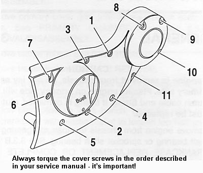
- Install each of the screws finger tight, and then torque them to spec in the sequence described in the service manual. This sequence is very important, don't skip this step!
- On 2003 and older models, install the timing plate into place using the mark you created on disassembly. However, be aware that this ignition timing setting will most likely not be correct!.
Cam sets vary and the ignition timing varies right along with them, I can't tell you how many times I've seen people make the mistake of assuming their ignition timing is still correct just because they
put the timing plate back on in the same position. Consider it as a starting point only, and set your timing properly once you get it running.
- Your pushrods are two different lengths: the longer pushrods go on the exhaust.
- Install your first rocker box with the piston for that cylinder positioned at compression TDC. Torque all the fasteners per the spec. As you bolt the rocker box down, the valves will
open. This is normal, as the lifters have oil in them that needs to bleed out. Normally the lifters will bleed down and allow the valves to close within 10-15 minutes of when the
rocker box is bolted down. Make sure the lifters have bled all the way down before rotating the engine! If you can get access to each pushrod, a sure fire way to know if the
lifter has bled down is to see if you can turn the pushrod by finger.
- Once the first rocker box is on and you're certain the lifters have bled down, rotate the engine to TDC compression on the other cylinder and repeat the process for that rocker box.
Again, make sure the lifters have bled down before turning the engine.
- Before you hit the starter button, rotate the engine at least two full revolutions by hand to make sure there is no mechanical interference. Starter motors are very unforgiving and if
something is wrong, you'll bend or break parts. If you feel any mechanical interference while turning by hand, disassemble as needed to determine the cause.
Checking Your Work: On some cam sets, the alignment marks leave room for interpretation. But you need to be sure it's done right before proceeding to button everything back up.
Fortunately, there's a simple solution to this dilemma. Using simple measurement tools, it's possible to verify that your cam timing is within the correct range. HAMMER PERFORMANCE has provided
instructions on this simple procedure. If you have any doubts at all that you've got the cams aligned and timed correctly, follow this simple procedure to make sure. It's a whole lot faster than taking
it all back apart.
|
Advanced Cam Installation
This section builds on the information provided above in the "Basic Cam Installation" section, so if you haven't read that yet, please do so. What we'll deal with here is how to install cams
with high lifts and/or high amounts of overlap, dealing with all the issues those things cause. If the cams you're installing are not designated as "bolt-in" from the manufacturer, some or all of the following
information may apply. If you're not sure if a given item applies to your application, please contact us for more information, we're happy to help.
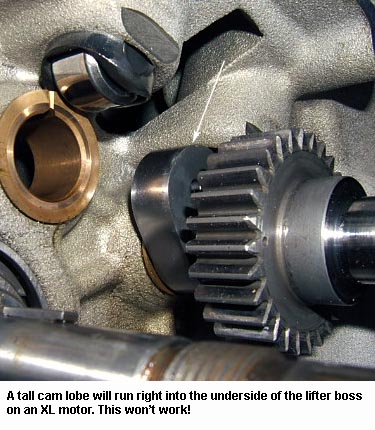
Lobe Swing Clearance: One of the very first things you'll run into when installing high lift cams is just a lack of clearance in the cam box for the taller lobe. There are two places where you're likely to get
contact in an XL motor:
-
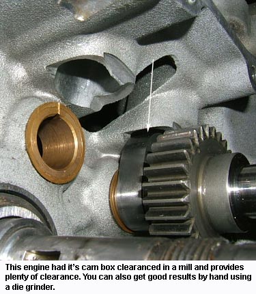
The lifter bosses: The lifter bosses extend down into the cam box a fair bit, and the cams may very well try to run into them. To correct this issue on an assembled motor, clean and tape off the cam box
area thoroughly, and then using a die grinder, carefully grind away at the underside of the lifter bosses. Be very careful to not slip and let the die grinder run into the cam bushings or pinion shaft or
pinion race. Grind until you've achieved at least .020" of clearance to the cam lobe. On a disassembled motor, this procedure is best accomplished on a milling machine.
HAMMER PERFORMANCE can handle this task for you.
 |
 |
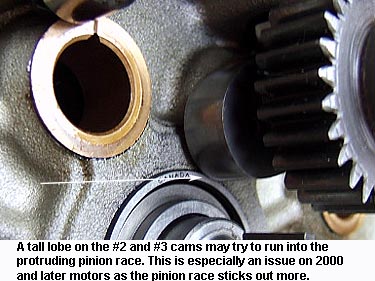
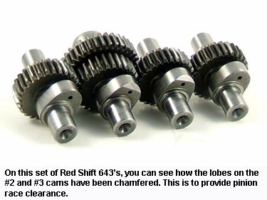
- The pinion race: This is mostly an issue on 2000 and later motors, as the pinion race sticks out from the case much more so than it does on the earlier motors. A tall lobe will try to run into it. We
do not recommend grinding on the race on an assembled motor! It's just too easy to damage the pinion race and get a whole bunch of debris into the bearing. We've seen people try to do this and end up
doing a complete tear-down to fix the damage. Instead, the best fix is to simply chamfer the back side of the lobe a little bit, as shown in the photo. This may seem odd, but we've done it numerous times and it's
never, ever, caused us an issue. Avoid encroaching on the lobe surface by more than .100", and be sure to deburr it thoroughly when finished.
Tappet Anti-Rotation Pin Clearance: This is another very common problem introduced by high lift cams.
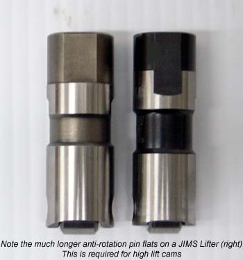 XL lifters are prevented from spinning in the bore by a flat area on the side of the lifter that rides up against a "tappet pin" in the case (for model years through 2005) or a locating device (for 2006-present) that
fits in from the top. Well, the flat on the lifter doesn't extend down particularly far on a stock lifter (see the picture), and as such, you run out of travel when the lift gets very tall. At somewhere around .570"
of valve lift is where most motors start seeing contact issues with either the tappet pin (2005 & older) or the anti-rotation piece (2006 & newer), assuming stock base circles on the cams (smaller base circle cams
often avoid this issue).
XL lifters are prevented from spinning in the bore by a flat area on the side of the lifter that rides up against a "tappet pin" in the case (for model years through 2005) or a locating device (for 2006-present) that
fits in from the top. Well, the flat on the lifter doesn't extend down particularly far on a stock lifter (see the picture), and as such, you run out of travel when the lift gets very tall. At somewhere around .570"
of valve lift is where most motors start seeing contact issues with either the tappet pin (2005 & older) or the anti-rotation piece (2006 & newer), assuming stock base circles on the cams (smaller base circle cams
often avoid this issue).
To determine if this is an issue in your situation, rotate the cam to the full open position, i.e. where the lifter is resting on the nose of the lobe. Now insert a magnet into the lifter bore from the top,
and pull up until it hits the tappet pin or anti-rotation device. You need a minimum of .060" of clearance here. If you can't pull the lifter up at least .060" before it hits the anti-rotation device, this
needs to be addressed.
The best solution for this problem is a set of aftermarket lifters that have extended flats, as shown in the picture. HAMMER PERFORMANCE carries these lifters. It's also possible
to mill the flat longer on your existing lifters, although this is a difficult procedure to do well. The material is rock hard and the lifter is a difficult thing to clamp tightly into the milling machine. We recommend
replacing the lifters with a high quality JIMS lifter instead.
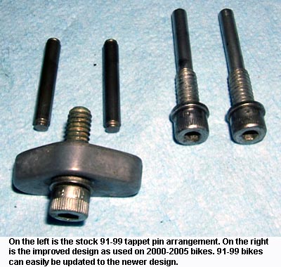 One other note about tappet pins: In 1991-1999 engines, the tappet pins are located on the outboard side of the lifter bore only. As such, they don't have a lot of strength or stability and they can
easily fail, particularly with inadequate clearance. In 2000, this design was improved by using a screw-in pin that's also longer, allowing it to be supported on the inboard side of the lifter bore as well. We
highly recommend updating your 91-99 tappet pins to the 2000-2005 style. This is best accomplished on a disassembled motor using an accurate drill press or milling machine, and HAMMER PERFORMANCE can handle this
service for you. But done carefully, it can also be accomplished on an assembled motor using a drill motor. Basically, you drill the hole deeper at the same diameter as the pin, and then drill and tap the outboard
portion only for the 1/4-20 threads of the screw-in tappet pin.
One other note about tappet pins: In 1991-1999 engines, the tappet pins are located on the outboard side of the lifter bore only. As such, they don't have a lot of strength or stability and they can
easily fail, particularly with inadequate clearance. In 2000, this design was improved by using a screw-in pin that's also longer, allowing it to be supported on the inboard side of the lifter bore as well. We
highly recommend updating your 91-99 tappet pins to the 2000-2005 style. This is best accomplished on a disassembled motor using an accurate drill press or milling machine, and HAMMER PERFORMANCE can handle this
service for you. But done carefully, it can also be accomplished on an assembled motor using a drill motor. Basically, you drill the hole deeper at the same diameter as the pin, and then drill and tap the outboard
portion only for the 1/4-20 threads of the screw-in tappet pin.
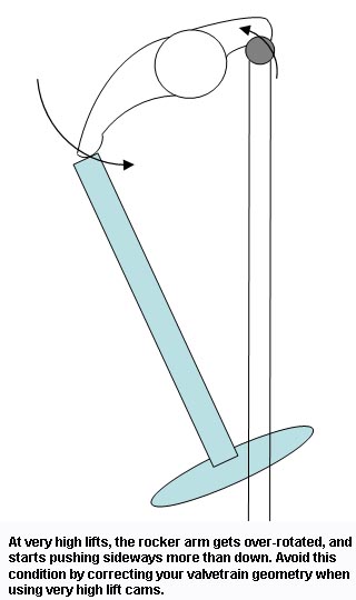 Valvetrain Geometry: As you get into high lifts, this starts becoming a concern. Essentially what happens is that as the valve gets pushed open farther and farther, the rocker tip, which travels in an
arc, starts moving sideways on the valve tip more than pushing down. You also start getting the same effect on the pushrod side of the rocker arm, where additional lift starts causing a lot of sideways motion because
you're not well centered in the arc. A more thorough discussion of the subject can be found here.
Valvetrain Geometry: As you get into high lifts, this starts becoming a concern. Essentially what happens is that as the valve gets pushed open farther and farther, the rocker tip, which travels in an
arc, starts moving sideways on the valve tip more than pushing down. You also start getting the same effect on the pushrod side of the rocker arm, where additional lift starts causing a lot of sideways motion because
you're not well centered in the arc. A more thorough discussion of the subject can be found here.
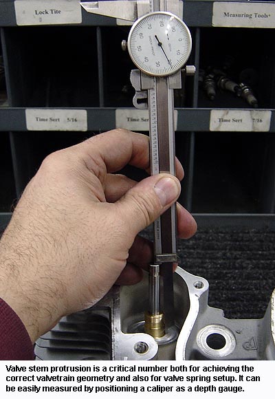
The corrective action for this problem is to extend the valve stem protrusion such that the tip of the valve is raised. You essentially want to raise the valve stem protrusion by about half the amount
you increase the valve lift, the idea being to keep a 90 degree angle between the valve stem and a line drawn between the valve tip and the center of the rocker shaft when at half lift. This gives maximum lift with
the least amount of side loading possible. Often times the valve stem protrusion needs to be raised anyway when using very high lifts just to get enough valve spring travel.
If HAMMER PERFORMANCE prepared your heads for you, and you told us what cams you're using, you're good to go, we've set your stem protrusion such that your geometry will work well. But if your heads have not been
prepared by someone who understands how to correct valvetrain geometry, or they were not prepared for the cam lift you intend to run, this is something you most definitely want to check. It starts really becoming a concern
at valve lifts of .575" and higher.
Rocker Box Clearances: Inside the rocker box, there's one clearance that's directly affected by valve lift, and another issue that's indirectly affected. A very common issue is for the pushrod side of the rocker
arms to make contact with the underside of the rocker box tops, particularly on 2003 and older XL's. This not only causes noise, but it can induce oil leaks as well. I've seen this issue occur on cam lifts as low as .536",
so don't ignore this check. It can be checked for by placing a little clay on the underside of the rocker box, doing a mock assembly, rolling the motor through the point of max lift, and then removing the top and measuring the
clay. Try to get at least .030" of clearance to ensure you'll get no contact. Another method for detecting this issue is to run the motor and look for the tell-tale marks, as shown in the pictures below. It's a very simple issue
to solve, fortunately, it takes only a few minutes with a die grinder.
The other issue you need to pay attention to in the rocker box is clearance between the spring and the side of the box. This is a concern for all years of XL's, and it's much more serious than a little noise or
oil leaks. It actually forces the valve to land sideways on the seat, which invariably causes seat recession, loss of valve seal, and less power. So ignore this issue at your own peril! The valve springs needed to handle
very high lift cams are typically larger in diameter than your stock springs, and taller installed heights to correct geometry or gain spring travel also compromise this clearance. Check it carefully!
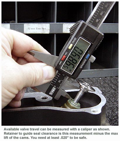 Retainer to Guide Seal Clearance: This is another very common clearance problem that pops up when using high lifts, particularly with stock valve guides. The underside of the valve spring retainer can
run into the valve guide seal at max lift.
Retainer to Guide Seal Clearance: This is another very common clearance problem that pops up when using high lifts, particularly with stock valve guides. The underside of the valve spring retainer can
run into the valve guide seal at max lift.
If you had HAMMER PERFORMANCE prepare your heads for you, and you told us the cams you'll be using, we've already made sure you have enough retainer to guide seal clearance and you don't need to be concerned
about making this measurement.
To check for this, simply install your valve and stem seal as normal, then put the retainer and keepers onto the valve stem without the spring installed. While pulling upward on the retainer, measure the distance
between the underside of the retainer and the top of the guide seal using a caliper. Make sure you have enough room to accommodate the cam's max lift spec with at least .020" of clearance left over.
If you don't have enough clearance, the corrective action is to either shorten the valve guide top, or to use a high performance valve guide such as those offered by HAMMER PERFORMANCE. These are shorter on the top
side specifically for this reason.
Valve Spring Setup:
 When selecting and installing valve springs for your high lift cams, there are two critical numbers you need to get right: seat pressure and coil bind clearance. Of course, if
HAMMER PERFORMANCE prepared your heads, and you told us what cams you'll be using, we've chosen an appropriate spring pack and already set them up for you. If not, read on.
When selecting and installing valve springs for your high lift cams, there are two critical numbers you need to get right: seat pressure and coil bind clearance. Of course, if
HAMMER PERFORMANCE prepared your heads, and you told us what cams you'll be using, we've chosen an appropriate spring pack and already set them up for you. If not, read on.
Spring pressure on the seat is a critical number for proper valvetrain control and life. Too little will cause seat bounce or valve float, risking damage to your engine, and too much increases the wear and
tear on your valvetrain components, as well as increasing the risk of a failure.
Sometimes a cam manufacturer will specify the number for you, but more often than not it comes down to experience with a given set of cams. As mentioned earlier, even when a cam manufacturer provides a number,
it should really only be considered a guideline, as the actual spring pressure needed to control the valvetrain at a given rpm is also affected by things like the weight of the various valvetrain pieces. If you're unsure
about the appropriate valve spring pressure for your application, contact us to discuss it, we have experience with most every XL cam grind and can provide a good number.
Every set of valve springs will have a seat pressure specified for it at a given installed height. Install the spring at a taller height and the seat pressure will be lower, or install it at a lower height
and the seat pressure will be higher. How much? This can be determined by looking at another spec, the spring "rate". For example, if a spring specifies it provides 200lbs at 1.850", and has a rate of 400lbs/inch,
then at .050" taller height (1.900") it will have .050" times 400 = 20lbs. less pressure, or 180lbs.
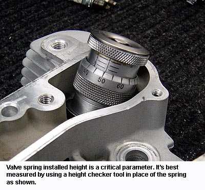 Spring installed height can be raised by increasing the valve stem protrusion in the head, which is done either by "sinking" the valve in it's seat, or by using a longer valve. Likewise, installed height can be reduced
by using a shorter valve or more commonly, by using valve spring shims under the spring.
Spring installed height can be raised by increasing the valve stem protrusion in the head, which is done either by "sinking" the valve in it's seat, or by using a longer valve. Likewise, installed height can be reduced
by using a shorter valve or more commonly, by using valve spring shims under the spring.
Spring installed height is one of the numbers that determines your coil bind clearance as well. Similar to the pressure specs, all springs have a specified "coil bind height". This represents how tall the spring is when
you compress it as far as it goes. Well, the difference between the installed height where you set up the spring and the coil bind height is your available spring travel.
Your available spring travel must exceed the maximum valve lift your cam provides, and the more it exceeds it by, the better. This number is known as "coil bind clearance". The minimum safe coil bind
clearance is .050", but for optimum spring life, .100" or more is desired.
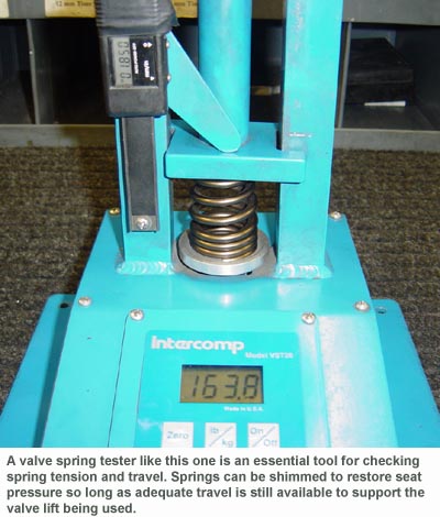 One final note about your springs: in high performance applications, valve springs will tend to fatigue over time, reducing their seat pressure. It's very common for racers to periodically test their valve springs
and shim as needed to restore the seat pressure back to where it needs to be for good valvetrain control. However, shimming the springs reduces the installed height which reduces the total travel available which
reduces the coil bind clearance. Once the spring has been shimmed to where there's not enough coil bind clearance remaining, it needs to be replaced.
One final note about your springs: in high performance applications, valve springs will tend to fatigue over time, reducing their seat pressure. It's very common for racers to periodically test their valve springs
and shim as needed to restore the seat pressure back to where it needs to be for good valvetrain control. However, shimming the springs reduces the installed height which reduces the total travel available which
reduces the coil bind clearance. Once the spring has been shimmed to where there's not enough coil bind clearance remaining, it needs to be replaced.
|
 Valve to Valve Clearance: This number reflects how close the valves get to each other during the overlap event, i.e. when the exhaust valve is almost closed and the intake valve has already started opening.
Since the valves on a Harley engine are not parallel to each other, valve to valve clearance is a concern. This clearance gets reduced not by a high max lift spec of the cam, but instead by high "TDC Lift" specs.
Valve to Valve Clearance: This number reflects how close the valves get to each other during the overlap event, i.e. when the exhaust valve is almost closed and the intake valve has already started opening.
Since the valves on a Harley engine are not parallel to each other, valve to valve clearance is a concern. This clearance gets reduced not by a high max lift spec of the cam, but instead by high "TDC Lift" specs.
As with many of the other clearances, this is something HAMMER PERFORMANCE checks and sets up for you when preparing your heads, so if you had us prepare your heads and you told us what cams you're using, you're
good to go, no need to be concerned.
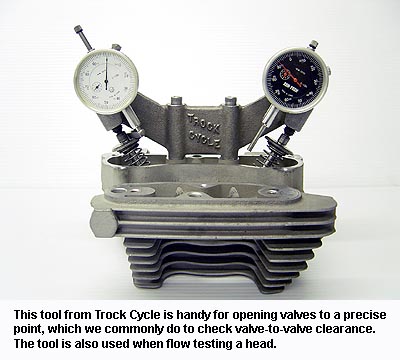
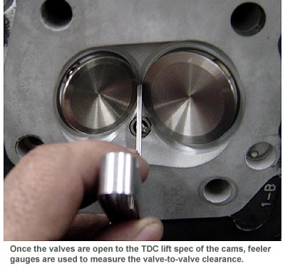 To check this number, simply open each valve to it's "TDC Lift" spec'ed number and then measure the distance between the valves with feeler gauges or even a spark plug gap measuring tool. Most people will tell
you that .050" to .060" of clearance is needed, but in reality, I know of racers that run it as tight as .030". If you have good control of the valvetrain, without valve float, you can get away with pushing it tight,
just stay on top of your valve spring pressures as described above.
To check this number, simply open each valve to it's "TDC Lift" spec'ed number and then measure the distance between the valves with feeler gauges or even a spark plug gap measuring tool. Most people will tell
you that .050" to .060" of clearance is needed, but in reality, I know of racers that run it as tight as .030". If you have good control of the valvetrain, without valve float, you can get away with pushing it tight,
just stay on top of your valve spring pressures as described above.
Valve to valve clearance is gained by "sinking" the valves in the heads, a procedure that is not without side effects. In particular, excessive sinking shrouds the valves, reducing low lift flow, and the act of
sinking as well as the unshrouding both increase the chamber size, reducing compression unless other corrective actions are taken. Like so many things when it comes to head prep, valve sinking done in moderation is
manageable, done it excess it's molesting. So there are times when we choose deliberately to push this clearance a little tighter, to avoid excessive valve sinking and it's drawbacks,
so long as we know all the pieces are in place for proper valvetrain control.
Valve to Piston Clearance: Valve-to-piston clearance is another critical clearance that gets compromised by high TDC lift figures on the cams, similar to valve-to-valve clearance described above. However,
unlike valve-to-valve clearance, this is not something that we can check and set for you when preparing your heads. You must perform this check yourself on your engine.
A minimum of .100" of clearance to the exhaust valve and .060" to the intake valve is required to be sure you won't get valve to piston contact in the normal case. If you get valve float, however, all
bets are off. Proper seat pressure for the application and the intended rpm are needed to prevent valve float (see above discussion of valve spring setup).
The best way to check valve to piston clearance is to "clay" the motor. This procedure is described in a separate HAMMER PERFORMANCE Tech Tips article.
|
More Things to Know
High lift cams, at high rpm's, and the spring pressure required to control the valvetrain under these conditions, places special demands on all of the components of your valvetrain. If you're going to be pushing
things hard like this, consider upgrading the following parts:
Lifters: We've tried about every high performance aftermarket lifter available, and we keep coming back to the JIMS units. In particular, the large axle design is well suited to handle the
loads placed on them by heavy valve springs. They are also one of the few brands on the market that have long anti-rotation pin flats. JIMS offers lifters in the traditional full hydraulic style, as
well as a full solid style for high rpm use, and a hybrid "Hydrosolid" style that's a combination of the two. We've used JIMS Hydrosolids very successfully in both our drag bikes and Bonneville bikes and
can heartily recommend them.
Pushrods: The stock pushrods in a Harley engine are barely adequate for the stock spring pressures. At higher than stock spring pressures, they flex, giving up lift in the process, and they can even
bend and fail. Replace them in any high performance application with a set of Sledge Hammer heat treated chrome moly pushrods. We stock these high quality pushrods in both adjustable and non-adjustable styles,
and we believe them to be the best pushrods on the market.
Rocker Arms: We have seen almost every brand of rocker arms have a failure when used with high lifts and high valve spring pressures, except for one. So that's the only brand we carry.
They are far from being the least expensive rocker arms on the market, but ask yourself how much a failure costs you! I know personally that I spend thousands to prepare my bikes, tow them to a race, pay entry fees, pay for motel rooms, and the
like. A part that fails because it's not up to the job costs me many times more than it's purchase price.
But beyond the strength issue, there's another good reason to move to roller tip rocker arms when using high lift cams. As described above in the Valvetrain Geometry section, at higher lifts the rocker arm pushes more
and more sideways on the valve. The result is an increase in valve side loading. Even when geometry is corrected you still get more side loading just due to the arc that the rocker arm tip travels in. Roller rocker arms
are great for reducing the friction at the valve tip thus reducing the side loading, helping valve guides last longer. We highly recommend roller tip rockers at valve lifts above .575".
Valve Springs: From the discussion above in the "Valve Spring Setup" section, hopefully you have enough understanding of spring specs to look beyond the simplistic ".xxx Lift" title that's so commonly
used to market valve springs. That number is essentially a shorthand statement giving someone's opinion (and yes, we do it too). But instead, look a little deeper, at the pressure spec for a given height, the rate, and the coil bind height, to determine if the spring
is suitable for your application.
Beyond those specs, though, there are other things to consider, in particular the alloy of the spring wire, the heat treatment, shot-peening, and nitriding. These things are all critical in helping to maximize
valve spring life, which is all about maintaining spring pressure for proper valvetrain control. HAMMER PERFORMANCE carries only the highest quality valve springs available, we have used these springs for years and
prefer them simply because they've proven themselves over and over in both our street and race motors. They are not the least expensive springs on the market, but again, consider the expense of a failure.
The other place where we see our competitors cut corners a lot is to use steel retainers instead of Titanium. The retainer sees a lot of movement and minimizing it's weight is critical. Only in the case of very
light beehive style springs do we ever use a steel retainer. All of the Ti retainers on HAMMER PERFORMANCE valve springs are the highest quality available, in fact we have never, ever had a failure with one.
Valves: The quality of the valves used in a high performance build is paramount. If you've ever experienced a valve stem failure on a cheap valve, you know exactly what I'm talking about. A broken
valve stem can literally take out an entire motor. HAMMER PERFORMANCE Sledge Hammer valves are made of the highest quality stainless alloys and we have proven them durable on our 200mph nitro burning
Bonneville bike and have never had a failure! You won't come close abusing them to that level on your street motor. HAMMER PERFORMANCE Striker series valves are made of the same high quality materials
but in the lighter 7mm stem design, perfect for most high performance street engines.
Degreeing Your Cams: One final word on cam timing. A specific set of cams as installed in a specific engine will almost never be spot on, in terms of the valve event timing or even the
lift figures for that matter, simply due to variations in the manufacturing of both the cams and the engine. Professional racers will often "degree" their cams, which is another way of saying they
attach a degree wheel and dial indicators and go in and measure the cam timing and lift directly. Cam timing is then altered to put it where the engine builder wants it for his specific application.
If you're interested in how to do this advanced procedure, HAMMER PERFORMANCE has provided a Tech Tips article describing how to "degree" your cams.
|
|
|
|

|
|
|